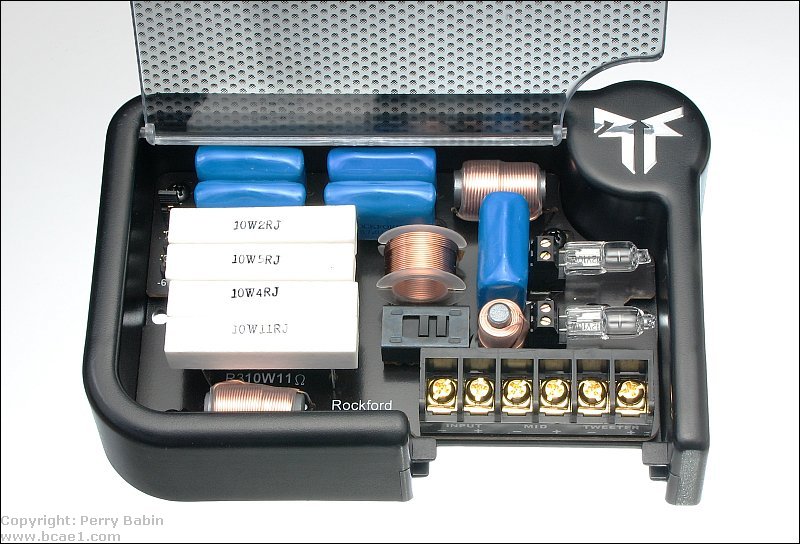
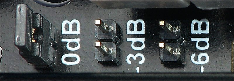
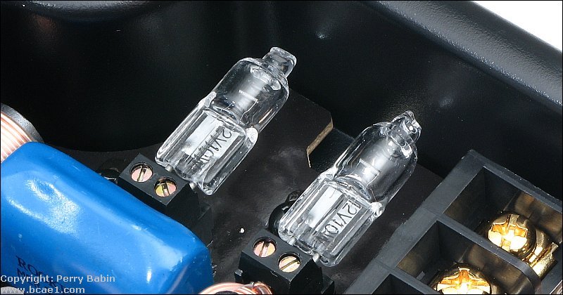
The following crossover is one from a relatively high-end speaker system. It allows you to set the tweeter output to 3 different levels. It allows you to select either 0° or 180° phase for the low frequency speaker and has protection for the tweeters.
6dB/octave High Pass Crossover:
The diagram below shows how capacitors would be used/connected in a high pass passive crossover system. Notice how one capacitor is in a positive wire and one is in a negative wire. Audio is an AC voltage which means that current flows both ways in the circuit. For a simple crossover like this, it doesn't matter which terminal you have the capacitor connected to. The same is true for the inductors in the next section.
The diagram below shows how inductors would be used in a low pass passive crossover system.
The diagram below shows how the inductor and capacitors would be used in a tri mode system.
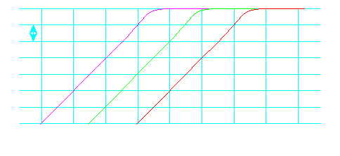
Position the mouse cursor over the crossover component values on each side of the graph to see how the slope slides as you change the crossover point. You should also notice how the coils roll off the high frequencies and the capacitors roll off the low frequencies. The straight line is the audio signal level with no crossover components in series with the speakers. The crossover points are roughly based on a 4 ohm speaker. The first time through, you should hold your mouse over each value until the image loads completely.
| CAPACITORS 100 microfarad 47 microfarad 22 microfarad 10 microfarad 4.7 microfarad | 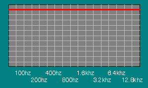 | COILS (inductors) 2.2 millihenry 3.3 millihenry 4.7 millihenry 5.6 millihenry 6.8 millihenry |
| Speaker Impedance 1 ohms 2 ohms 4 ohms 8 ohms | 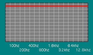 |
This section shows the math involved in selecting the proper coil for your particular speaker system. This is the formula needed.

Pi=3.14....
Frequency = The desired 3dB down (crossover) point
Inductor = Value of proper coil - value given in henries (multiply by 1000 to convert to millihenries)
For this example, let's choose 4 ohms as the speaker's rated impedance. We will use 200hz as the desired crossover point.
Value of the coil=4/(2*3.14*200)
Value of the coil=3.18 millihenries
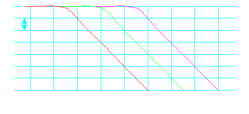
The output level of a 4 ohm speaker with a 3.18 millihenry coil in series with it, would follow (approximately) the red line. If it were a 4 ohm resistor, instead of a speaker, the frequency response would follow the line exactly. A speaker has inductance in it's voice coil which would make finding the exact response difficult but this equation will get you close to the desired response.
This diagram shows the rolloff characteristics of 3 different passive crossovers each of which consist of a single capacitor (of different values) creating the rolloff. The red line shows the frequency response of a filter with a 3200hz crossover point. The green line has a crossover point of 1200 hz. The purple line has a crossover point of 400hz. The rate of rolloff is only 6dB/octave.
This section shows the math involved in selecting the proper capacitor for your particular speaker system. This is the formula needed.

Pi=3.14....
Frequency = The desired 3dB down (crossover) point
Capacitor = Value of proper capacitor - value given in farads (multiply by 1,000,000 to convert to microfarads)
For this example, let's choose 4 ohms as the speaker's rated impedance. We will use 1200hz as the desired crossover point.
Value of the capacitor=1/(2*3.14*1200*4)
Value of the capacitor=33 microfarads
The output level of a 4 ohm speaker with a 33 microfarad capacitor in series with it, would follow (approximately) the red line. Again, if it were a 4 ohm resistor, instead of a speaker, the frequency response would follow the line exactly. A speaker has inductance in its voice coil which would make finding the exact response difficult but this equation will get you close to the desired response.
- Capacitors in series:
The total value is less than the value of the smallest capacitor. If the values of all of the caps are equal, simply divide the value of a single capacitor by the total number of caps in series. Two 10uf (uf=microfafads) capacitors in series is 5uf total.
- Capacitors in parallel:
The total value is the value of the individual capacitors added together. Two 10uf capacitors in parallel is 20uf total.
All capacitors have a maximum voltage rating. Capacitors used for crossovers are no different. Capacitors rated for use at 100 volts are OK to use with virtually all car audio amplifiers. For amplifiers rated to produce more than 2500 watts into 4 ohms, you will need higher voltage capacitors. 50 volt caps are good for amplifier rated up to 600 watts into 4 ohms. There is a calculator on the 'damping factor' page of this site which will calculate the voltage needed to produce a given power into a given load. Use capacitors rated higher than the voltage given by the calculator. Polarized vs Non polarized Capacitors:
Most capacitors are non polarized (bi-polar) but there are a few that are polarized and have a positive and a negative terminal. Polarized capacitors should never be used for audio transmission (or coupling). The most common and least expensive capacitors used in crossovers are 'electrolytic' capacitors. Electrolytics can be found in both polarized and non polarized versions. When you buy electrolytic capacitors for use in passive crossovers, make sure that they are non polarized. Other capacitors used in passive crossovers such as Mylar, polypropylene and polyester are non polarized.For more information on higher order crossovers, go The following demo shows how the crossover's output signal level changes with a change in input frequency or a change in the crossover point. The output sine waves indicate power output. A sine wave half as tall as the original indicates that the speaker would receive only half power at that frequency and crossover point.
No comments:
Post a Comment