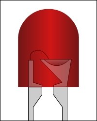
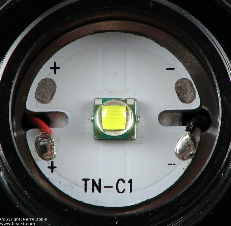
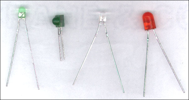
 An LED is a special semiconductor which emits light when current is passed through it. There are many different physical styles. The emitted color spectrum is usually very narrow. It can generally be specified as a specific wavelength in the electromagnetic spectrum. The emitted color selection is somewhat limited. The most commonly available colors are red, green, amber, yellow, blue and white. The red, green, yellow and amber have a working voltage of approximately 1.8 volts. You can refer to the data sheet for each LED to find the exact value. The actual working voltage is determined by the breakdown voltage of the particular semiconductor material. An LED is a special semiconductor which emits light when current is passed through it. There are many different physical styles. The emitted color spectrum is usually very narrow. It can generally be specified as a specific wavelength in the electromagnetic spectrum. The emitted color selection is somewhat limited. The most commonly available colors are red, green, amber, yellow, blue and white. The red, green, yellow and amber have a working voltage of approximately 1.8 volts. You can refer to the data sheet for each LED to find the exact value. The actual working voltage is determined by the breakdown voltage of the particular semiconductor material.Colored LEDs: Multi-color LEDs and some white LEDs have multiple dies (the semiconductor material that produces the light). The color can be changed by illuminating the dies at various levels. White LEDs are also sometimes blue LEDs with added phosphors to make them emit white light. LED Lenses: LEDs often share a common shape. The plastic housing is shaped to produce a specific viewing angle. For any given LED die, the light pattern can be shaped to provide a very tight beam or a wide beam by changing the shape of the lens (the plastic housing, in front of the die). Most LEDs are designed for very low power consumption and low output (light output). Even though the LEDs sold as super-bright LEDs may seem bright if you look directly at them, they are still low power LEDs. The 'super-bright' LEDs are typically in a standard LED package and require no heatsink to operate at the recommended current. LEDs that are really bright can be seen for miles. These are typically used in flashlights. One example is the Cree XM-L LED (datasheet HERE). The following image shows the XM-L LED in a ThruNight Catapult V2. The LED is soldered to a heatspreader. This increases the effective surface area of the LED to promote greater thermal transfer. The heatspreader is flat against a large piece of aluminum that serves as a heatsink. Between the aluminum, there is a layer of thermal/heatsink compound. When the reflector assembly is screwed on, it presses the heatspreader against the heatsink. All of this is required for a high power LED to operate at full power.  LED Drive Current: When using an LED in a circuit, the exact working voltage is not extremely important. The most important thing is the current flow through the LED. The current through the diode must be limited by a series resistor. An LED has a specified maximum continuous current rating. Most LEDs can pass 20 milliamps continuously without damage but it is not necessary to use the maximum rated current. An LED will light with much less current. The difference between high current and low current will be the brightness of the LED. To decide what resistor value is needed, you subtract the working (forward) voltage from the power supply voltage and divide that number by the desired current flow. Working voltage (Vf)=1.8 volts Desired current flow=15ma (.015 amps) Power supply voltage=12 volts 12-1.8=10.2 10.2/.015=680 ohms A 680 ohm resistor will limit the current to a safe level although I would probably use a 1000 ohm in a vehicle because the charging system voltage would be higher than 12 volts. Any resistor between 680 and 4700 ohms would probably work fine. Choose a resistor with a power rating greater than or equal to the power dissipation given by the calculator above. The diagram below shows the parts of an LED. You must also know that an led has polarity. This means that the positive and negative terminals must be connected correctly for it to operate properly. As you see in the diagram below, if the polarity is reversed, the LED will NOT light. If the reverse voltage is beyond what the LED was designed to handle, it may be damaged. Click on the 2 buttons in the demo below to see the LED operation with either polarity. The image below shows a few different styles.  |
REGARDING ABOUT ALL KIND OF MEDICAL EQUIPMENT'S SALES , SERVICE, INSTALLATION , MAINTENANCE, CALIBRATION AND MEDICAL COLLEGE ALL PRODUCT
Friday, 15 June 2012
Function of Light Emitting Diodes - Street Light
Subscribe to:
Post Comments (Atom)
No comments:
Post a Comment