To bridge amplifiers that have signal only on the positive speaker terminals, if you want to bridge two channels to one load, you have to use some means to invert the signal on one channel (remember the old 'bridging modules' for Orion amplifiers?). Today's bridgeable multi-channel amplifiers (2 or more independent channels) have an inverted channel or an on-board switch (to invert the output of the amp) as part of their design to allow bridging. For many amplifiers, the left positive and right negative are are the signal outputs. A few use the left negative and the right positive. Mono amplifiers that have only one channel must have a way to invert the signal on the output of the amplifier. To bridge two mono amps, you invert the output of one of the two amplifiers and connect one amplifier's output to the positive speaker terminal and the other amplifier to the other speaker terminal. Note: Before we go any farther let me say this... It it NOT necessary to bridge a multi-channel amplifier to make it produce maximum power. Bridging is simply one option. If an amplifier is 2 ohm stereo stable (and therefore 4 ohm mono stable), it will produce the same power into a 2 ohm stereo load as it will into a 4 ohm mono load. Many people feel that they have to connect every multi-channel amplifier they own (generally 2 ohm stereo stable or 4 ohm mono stable) in a 2 ohm mono configuration. These are generally the same people who have owned (and destroyed) many amplifiers. This is because very few amplifiers (especially Class A/B amplifier) are capable of safely driving a 2 ohm mono load. The reason why a 2 ohm mono configuration is dangerous to most multi-channel amplifiers will be covered a bit later. As was stated previously, bridging an amplifier simply means using two output terminals both of which have signal on them (there's usually one each from the left and right channels of the amplifier). It is usually done to increase the power output to a speaker or to utilize both channels of a stereo amplifier if you only have one woofer. To fully understand how amplifiers are bridged, we should first cover "phase" as it applies to audio amplifiers. The following diagram shows 3 sine waves that are out of phase with each other, to varying degrees. 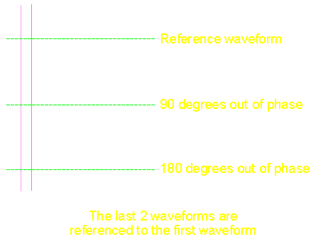 The following diagram shows how the waveform relates to the 360 degrees of a complete circle (one complete cycle of the waveform). 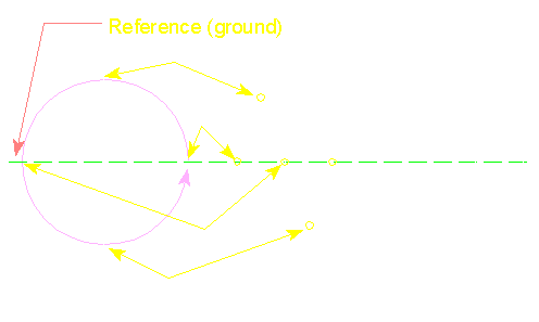
This diagram shows 2 waveforms and the reference to the 360º cycle. 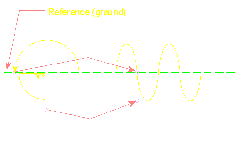 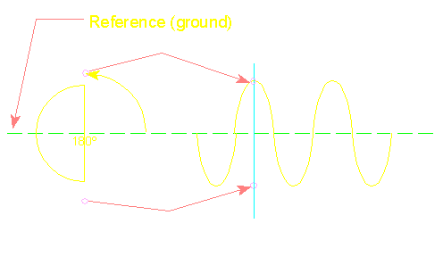 In the diagram below, there are 2 sine waves. The first waveform is the "normal" sine wave. The bottom waveform is "inverted" or 180 degrees out of phase with respect to the "normal" signal. In a 2 channel (left and right) bridgeable amplifier, one output is in phase with the input signal and the other channel is inverted. In most bridgeable amplifiers, especially American made amps, the left positive has the in phase signal and the right negative has inverted signal.  In the next image, you can see that both negative terminals, on the non-bridgeable amp, go to a reference point inside of the amp. This means that there is no signal on those connections. In many amplifiers, the reference is actually 'ground'. You will also see thatboth positive terminals have a normal (non-inverted) signal on them. The left channel of the bridgeable amplifier is set up just like the left channel of the non-bridgeable but the right channel of the bridgeable amp is where you will see the difference. Notice that the right negative has the signal on it, also notice that the signal is inverted (flipped upside down). In the following diagram, you can see a speaker connected in a normal configuration and another speaker connected in bridged mode. You can see that the peak voltage available to the normal speaker is 1/2 the voltage available to the bridged speaker (between points A and B). The normal connection uses 1 signal lead and the reference (ground). Thebridged speaker uses 2 signal leads. Since the voltage available to the bridged speaker is doubled (between points C and D), the power driven into the speaker can be four times as much as the normal connection (remember that P=E2/R). 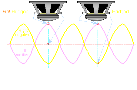 Refresher: Remember that the AC voltage across a speaker's voice coil is what determines the amount of power dissipated by the voice coil (and ultimately how much sound pressure the speaker will produce). In other words, when more voltage is applied to a speaker, the speaker will play louder. If one speaker terminal is connected to a reference point which has no signal (commonly referred to as ground-indicated by the red line) and the other speaker terminal is connected to the signal (speaker output) lead of the amplifier, you will only be able to get half of the power supply's total voltage across the speaker at any point in time. Realize that a speaker must move equally in both directions from its point of rest. If the amplifier's power supply output is 40 volts total or ±20 volts with "ground" as the reference, the maximum instantaneous voltage that can be applied across the non-bridged speaker's terminals is 20 volts. Well this would be true if the amplifier components were 100% efficient. In the real world the output voltage would be somewhat lower due to inefficiencies but we won't worry about inefficiency right now. For now assume that the full power supply voltage (positive or negative) can be driven into the speaker. If you remember the section on Ohm's law, you will understand that the amp will only be able to produce 100 watts (peak power) into a 4 ohm speaker. P=E*E/R Power=(voltage across speaker*voltage across speaker)/(resistance of the speaker) Power=(20*20)/4 ohms Power=100 watts NOTE:
Now, what if you have only a single 4 ohm speaker and a 2 channel NON-bridgeable amplifier with sufficient current output capability to drive a 2 ohm load on each of its output channels? You know that the amplifier could produce MUCH more (and also maximum) power into four 4 ohm speakers (which would be equal to a 2 ohm load per channel), but maximum power would not be produced into the single 4 ohm speaker on a single output channel (i.e. left OR right). To produce maximum power into a single 4 ohm speaker (without increasing the rail voltage) you could simply invert the signal of one channel and bridge the speaker on the amplifier. This is why some of the older amplifiers used a 'bridging module' (it inverted the signal going to one channel). It is very easy to invert one channel when designing an amplifier and it makes the amp much more versatile. When one channel is inverted, it's output voltage is of the same magnitude as the "normal" channel but is of opposite polarity (as indicated by the violet and yellow lines of the following diagram).  P=E*E/R Power=(40*40)/4 ohms Power=400 watts You can see that this is considerably more power! (100 watts un-bridged and 400 watts bridged) I=V/R I=20/2 I=10 amperes If we take a single 4 ohm speaker and bridge it on that same amplifier, the amplifier will be able to apply twice the voltage across the speaker. This is because while one speaker terminal is being driven positive (towards the positive rail), the other terminal is being driven towards the negative rail. This will allow the entire power supply voltage to be applied to the speaker's voice coil. It will now be able to drive the 4 ohm speaker with 40 volts instead of 20 volts in the previous example. Back to Ohm's law... I=V/R I=40/4 I=10 amperes The same amount of current flows through the output transistors whether the amplifier is driving a 4 ohm mono load or 2 ohm stereo load. As far as the amplifier is concerned, they are the same load. NOTE: Some people say that when an amplifier is bridged onto a 4 ohm load, it 'sees' a 2 ohm load. While it is true that the same current flows whether the amp is bridged on a 4 ohm load or a 2 ohm stereo load, the amplifier is driving a 4 ohm load across its outputs. A single 4 ohm speaker can never be a 2 ohm load. |
|
No comments:
Post a Comment